

First LED: Pin, sleep and toggle
Goal
You will blink the on-board LED, connect three external LEDs with resistors and write a "running light". You will meet the Pin class, the sleep functions and a way to blink several LEDs at different speeds without blocking your program.
Parts you need
- a Pico connected to your computer (or just the simulator)
- LEDs: red, yellow, green
- 3 resistors, 330 Ω
- a breadboard, 4 jumper wires
2.1. The on-board LED
The Pico has a built-in green LED. In MicroPython it is called "LED":
from machine import Pin
from time import sleep

led = Pin("LED", Pin.OUT)   # pin as an output

while True:
    led.on()                # high state: 3.3 V, the LED lights up
    sleep(0.5)              # wait half a second
    led.off()               # low state: 0 V
    sleep(0.5)
What is going on here:
Pin("LED", Pin.OUT)configures the pin as an output. On the Pico and Pico 2 it is GP25. On the Pico W and Pico 2 W the LED is connected to the wireless chip, not to GP25, so always write"LED", never25. That name works on every model.on()andoff()are shortcuts forvalue(1)andvalue(0).sleep()from thetimemodule takes seconds (fractions too). There are alsosleep_ms()andsleep_us()for milliseconds and microseconds.
A shorter version, using toggle(), which flips the current state:
from machine import Pin
from time import sleep_ms

led = Pin("LED", Pin.OUT)

for i in range(10):
    led.toggle()
    print("step", i)
    sleep_ms(300)

led.off()
print("Done.")
This program ends by itself after ten steps (five blinks) and switches the LED off at the end.
2.2. A resistor for the LED
An LED conducts current in one direction only and has an almost constant voltage drop, U_F (about 2 V for a red one). The resistor has to take up the rest of the voltage, and its value sets the current:
R = (U_pin − U_F) / I = (3.3 V − 2.0 V) / 0.004 A ≈ 325 Ω  →  330 Ω
I = (3.3 V − 2.0 V) / 330 Ω ≈ 3.9 mA
4 mA is enough for an ordinary 5 mm LED to shine clearly, and it fits within the Pico's default pin drive strength (4 mA). The whole RP2040 can supply about 50 mA from all its pins combined, so three LEDs at 4 mA each leave a safe margin.
| Resistor | Current (U_F = 2.0 V) | Comment |
|---|---|---|
| 220 Ω | ≈ 5.9 mA | brighter, still safe for a single LED |
| 330 Ω | ≈ 3.9 mA | the value used in the course |
| 1 kΩ | ≈ 1.3 mA | dimmer, but modern LEDs are still visible |
⚠️ Blue, white and bright green LEDs have a U_F of about 3 V. At 3.3 V from the pin only 0.3 V is left across the resistor, so they glow very faintly. For this course pick an ordinary green LED (U_F about 2.1 V).
2.3. Connecting three LEDs
Each LED has its own resistor. The circuit is: GP pin → 330 Ω resistor → anode (the longer leg) → cathode (the shorter leg, next to the flat edge of the casing) → GND.
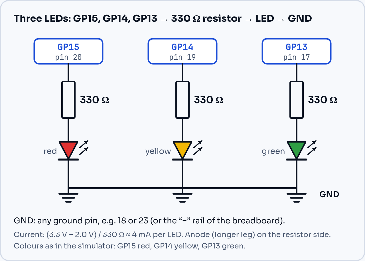
Fig. 2.1. Three LEDs with resistors. The simulator has the same pins and colours.
| GP pin | Physical pin | Component |
|---|---|---|
| GP15 | 20 | 330 Ω resistor → anode of the red LED |
| GP14 | 19 | 330 Ω resistor → anode of the yellow LED |
| GP13 | 17 | 330 Ω resistor → anode of the green LED |
| GND | 18 or 23 | the "−" rail of the breadboard ← cathodes of all the LEDs |
On the breadboard: place the Pico across the central groove so that each pin lands in a separate row of holes. Connect a GND pin to the "−" rail and plug the LED cathodes straight into the "−" rail. The resistor can sit on either side of the LED; what matters is that it is connected in series.
2.4. Running light
from machine import Pin
from time import sleep_ms

leds = [Pin(15, Pin.OUT), Pin(14, Pin.OUT), Pin(13, Pin.OUT)]  # red, yellow, green

try:
    while True:
        for led in leds:
            led.on()
            sleep_ms(200)
            led.off()
except KeyboardInterrupt:
    for led in leds:
        led.off()           # after Stop, switch everything off
    print("Stopped.")
Stop (in the simulator, the browser and Thonny) sends Ctrl+C, and MicroPython then raises a KeyboardInterrupt exception. Without the try/except block the LEDs would stay in their last state, because after a program ends a pin keeps the value it was set to.
2.5. Blinking without blocking: ticks_ms
sleep() stops the whole program. If you want to blink two LEDs at different speeds, and in later lessons also react to a button, it is better to check how much time has passed:
from machine import Pin
import time

red = Pin(15, Pin.OUT)
green = Pin(13, Pin.OUT)

t_red = t_green = time.ticks_ms()

while True:
    now = time.ticks_ms()
    if time.ticks_diff(now, t_red) >= 500:     # every 500 ms
        red.toggle()
        t_red = now
    if time.ticks_diff(now, t_green) >= 150:   # every 150 ms
        green.toggle()
        t_green = now
    time.sleep_ms(5)                           # a short pause; the loop still runs 200 times a second
ticks_ms() is a millisecond counter since the board started. After a while it "wraps around" to zero, so always calculate the difference with ticks_diff(newer, older) and not with plain subtraction.
2.6. Timer: blinking in the background
machine.Timer calls a function at a set interval, independently of the main program:
from machine import Pin, Timer

led = Pin("LED", Pin.OUT)

def blink(t):
    led.toggle()

timer = Timer(period=250, mode=Timer.PERIODIC, callback=blink)
print("The program has finished, but the LED keeps blinking. Stop it with the Stop button.")
The program ends straight away, but the timer keeps running until Stop (in the simulator) or timer.deinit(). A function called by a timer should be short: no sleep and no long calculations.
Common mistakes
Pin(25)does not blink on a Pico W / Pico 2 W: there the LED is not on GP25. WritePin("LED", Pin.OUT).sleep(500)instead ofsleep_ms(500): the program waits 500 seconds.sleep()takes seconds.- The LED does not light up: it is the wrong way round (turn it the other way round; at 3.3 V a reversed LED comes to no harm), the resistor and the LED leg are in different breadboard rows, or GND is not connected to the "−" rail.
- The LED is on all the time, whatever the program does: a wire is in the 3V3(OUT) or VBUS pin instead of a GP pin. Check the physical pin number in Figure 1.1.
- No resistor: the LED is very bright and gets hot. Unplug the USB cable at once and add a resistor.
- Wrong GP number:
Pin(20)is GP20, not physical pin 20. In code always use the GP number.
Exercises
- SOS: send SOS in Morse code with the red LED (3 short flashes of 200 ms, 3 long ones of 600 ms, 3 short, then a 1.5 s pause).
- Traffic lights: red (3 s) → red + yellow (1 s) → green (3 s) → yellow (1 s) → start again.
- Binary counter: show the numbers 0 to 7 on the three LEDs (green = bit 0, yellow = bit 1, red = bit 2). Hint:
(n >> 1) & 1gives bit number 1 ofn. - Modify the program from 2.5 so that the third LED (yellow) blinks every 1 s.
Summary
Pin(number, Pin.OUT) turns a pin into an output, and on(), off(), value() and toggle() change its state. Address the on-board LED by the name "LED". Always connect an external LED through a resistor: 330 Ω gives about 4 mA at 3.3 V. For several independent rhythms use ticks_ms() and ticks_diff() instead of sleep(), and Timer for background work.